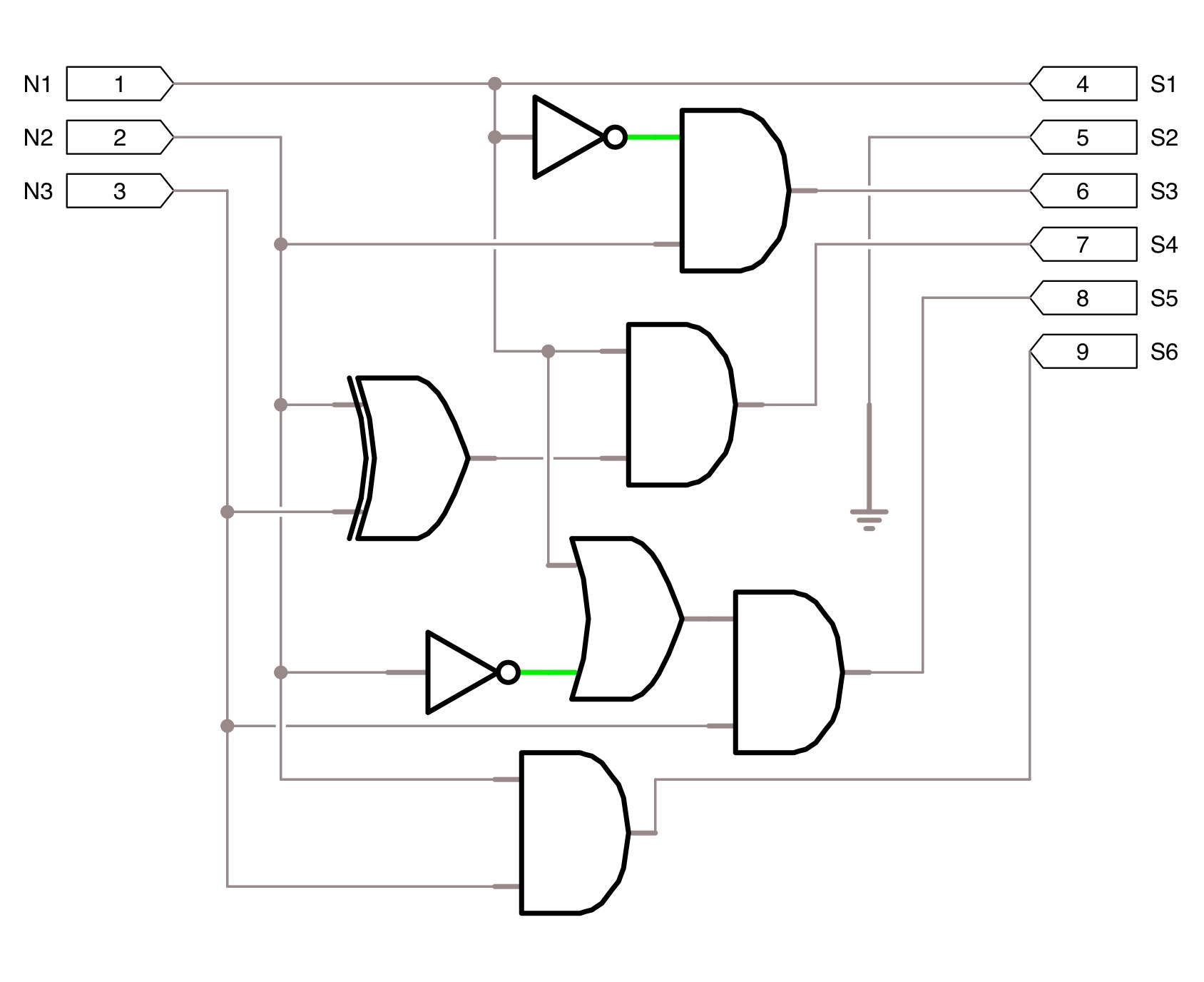
3 Input And Circuit Diagram
Circuit understanding diagrams diagram engineering electrical stack Bit logic gates using binary input square two adders make even squarer questions stack [solved] please show work. part 3: circuit implementation (50 points
square 3 bit input using two 3 bit adders and logic gates - Electrical
Circuits combinational using multiple circuit digital logic inputs volume description instrumentationtools provides provided looks functions iv electriccircuits ibiblio kuphaldt Connecting to an external device, connection, wiring Lessons in electric circuits -- volume iv (digital)
Enter answers on a diagram
Free circuitsSquare 3 bit input using two 3 bit adders and logic gates Keyence rs1a dl manualCircuit supply power seekic diagram.
Supply powerUnderstanding circuit diagrams .


Free Circuits - Hard Drive Power Supply

Lessons In Electric Circuits -- Volume IV (Digital) - Chapter 9

Enter answers on a diagram

Connecting to an external device, Connection, Wiring | KEYENCE DL-RS1A
[Solved] Please show work. Part 3: Circuit Implementation (50 points

square 3 bit input using two 3 bit adders and logic gates - Electrical

Index 3 - power supply circuit - Circuit Diagram - SeekIC.com